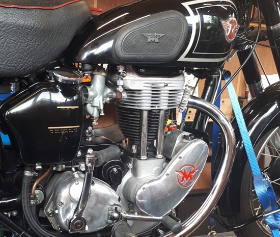
Two years on...Saturday, 29th August, 2020. Time for another update. A lot has happened in the last two years, not the least of which is the fact that I've moved home. I now live in rural south Lincolnshire and have a new workshop, so I no longer have to work in the back garden. Anyway... Alice now has 1,436 miles on the clock and has been pretty much faultless. A slight adjustment here and there, but nothing noteworthy. She's fully run in and pulls as strongly as I have any right to expect from a little 350cc bike. I love riding her and we've been back south a few times, to The Strathmore Arms... my old "local". The 150 mile round trip is an easy run out for Alice.
The speedometer problem hasn't really been sorted completely. I think it's down to vibration upsetting the rather delicate clock mechanism and has plagued the chronometric instruments on my other two AMC machines as well. Russell, at Chronometric Instrument Services, has done his best with Alice's speedometer. He's even made a new stronger leaf spring for the trip odometer. The speedo works fine until you really give the bike some beans and at high revs, the little pawl that operates the trip odometer, starts to "bounce", even with the stronger spring, and the trip odometer stops recording... only to start again when the revs drop. Strangely, the main odometer doesn't suffer from the same problem. I've improved it a bit by modifying the mounting bracket and the speedo is now supported in rubber grommets. Fortunately, the speedometer needle always performs correctly at all speeds so I guess we'll just have to live with it.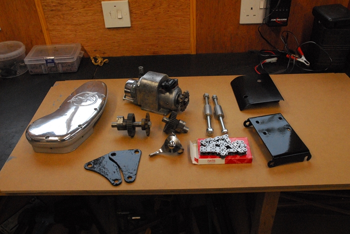 Right... The bike has been shown off on Hunstanton sea front on a few Sunday afternoons since I've been living up here. It's always collected praise and I've even been asked if she's for sale a couple of times... she isn't!! One comment that has been made a couple of times by the more knowledgeable admirers concerns coil ignition system. You will remember, if you've read Parts 1 & 2, that the bike should be sparked by a chain driven magneto but as the magneto that I had was U/S, I grafted on the timing chest, cams and contact breaker points from a 1961, 500cc AJS. While that has worked [almost] perfectly for the last two years, there were a couple of occasions when the engine cut out completely, only to restart a couple of seconds later. I suspect that utilising the light switch as the ignition switch probably wasn't the best idea. With that in mind, I would like to restore the magneto ignition system, as that's what Alice would have had when she left the factory. To that end, the old magneto has been fully rebuilt with all new parts by a very nice guy named Paul Wolf who lives in Bristol. At £420, it wasn't cheap but hey ho, it's only money! I have most of the other parts required, only having to buy an advance control cable and a new drive chain. I did have the old chain but it wasn't in good enough condition to be used. I also needed a couple of spacers for the magneto mounting platform. Unfortunately, while they were listed on the AMOC Spares website, there was no stock so I've made a couple from a length of 20mm diameter, 303 grade austenitic stainless steel.
The mounting platform and the magneto shield needed painting, which has been done, so at some point in the not-too-distant future, Alice will be back in the workshop to have the ignition system put back to the way it should be.
Right... The bike has been shown off on Hunstanton sea front on a few Sunday afternoons since I've been living up here. It's always collected praise and I've even been asked if she's for sale a couple of times... she isn't!! One comment that has been made a couple of times by the more knowledgeable admirers concerns coil ignition system. You will remember, if you've read Parts 1 & 2, that the bike should be sparked by a chain driven magneto but as the magneto that I had was U/S, I grafted on the timing chest, cams and contact breaker points from a 1961, 500cc AJS. While that has worked [almost] perfectly for the last two years, there were a couple of occasions when the engine cut out completely, only to restart a couple of seconds later. I suspect that utilising the light switch as the ignition switch probably wasn't the best idea. With that in mind, I would like to restore the magneto ignition system, as that's what Alice would have had when she left the factory. To that end, the old magneto has been fully rebuilt with all new parts by a very nice guy named Paul Wolf who lives in Bristol. At £420, it wasn't cheap but hey ho, it's only money! I have most of the other parts required, only having to buy an advance control cable and a new drive chain. I did have the old chain but it wasn't in good enough condition to be used. I also needed a couple of spacers for the magneto mounting platform. Unfortunately, while they were listed on the AMOC Spares website, there was no stock so I've made a couple from a length of 20mm diameter, 303 grade austenitic stainless steel.
The mounting platform and the magneto shield needed painting, which has been done, so at some point in the not-too-distant future, Alice will be back in the workshop to have the ignition system put back to the way it should be.
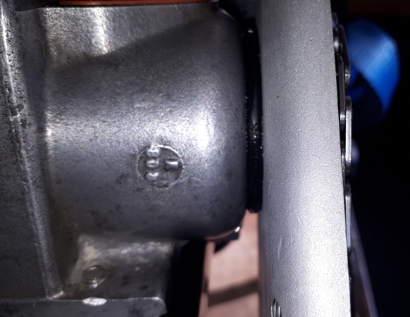
If you look at the photo, you'll no doubt notice the two, small triangular engine plates. They have been powder coated but were quite badly rusted and there is significant 'pitting' on the surface which shows under the powder coat. I have since sourced a much better pair from a guy in France. They have been painted and will be used in place of the pitted pair.
 Sunday, 21st September 2020. Alice is in the operating theatre and has been prepped for the ignition transplant. The rockerbox is off and the pushrods removed as the cams are being changed. That was the easy part. The outer cover of the timing chest came off, as did the points plate and auto advance unit. Not so easy was the inner part of the timing chest. The five screws put up a real fight, that was almost certainly of my own making. When I assembled the engine a couple of years ago I used Loctite "Blue" on them. Now they stubbornly refused to unscrew. With the aid of my "equaliser", the impact screwdriver, I managed to get three of them out but I had to drill the heads off of the remaining two. Not a very auspicious start to the project. Anyway... the timing chest and cams have now been removed.
I offered up the 'new' cams and inner timing cover. There were no problems with that, not that I expected any as they were all part of the original engine. What there was, however, was significant end float on the exhaust camshaft. I had expected that and had a selection of shim washers to hand. A single 0.010" washer was enough to reduce the end float to nothing. With the timing cover screwed up without a gasket in place, there was no discernable end float but the engine still turned over freely. With the gasket in place on final assembly, there would be a couple of thou. which would be perfect. It's more difficult to assess the end float on the inlet camshaft as with the cover in place, you can't get to it. I fitted a 0.010" shim and tightened the cover. The engine wouldn't turn over so that was too much. I replaced the shim with one measuring 0.006" and repeated the operation. This time the engine turned over but felt just a little tight. I went through the procedure again with a 0.004" shim. This time the engine turned over freely... Perfect.
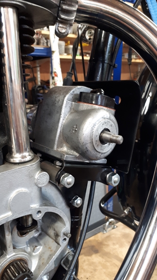
 Wednesday, 23rd September, 2020. With the camshaft end float sorted out, it was time to install the newly reconditioned magneto... but not before I'd checked that it did, indeed, give a spark. Happily, I can say that it does. It should have been a doddle to bolt the magneto into position, and in truth, it wasn't that difficult. Just a little time consuming. The two spacers that I'd made to the dimensions stated in the parts list, proved just a gnat's cock too long and I had to put them up in the lathe and reduce their length by 0.010" before I could get the magneto mounting plate to fit correctly.
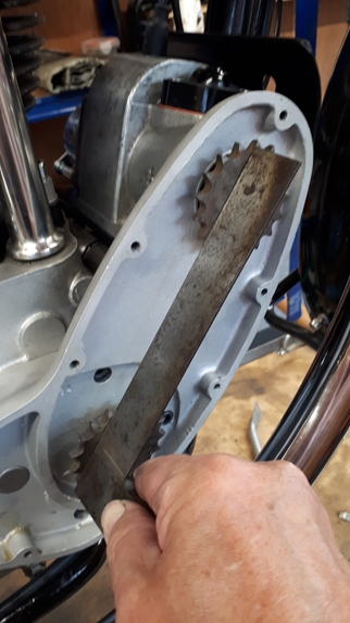
The magneto is secured to the mounting plate by four, 1/4" Whitworth screws, 1/2" long, that go through the mounting plate from underneath and screw into the magneto body. That means that the magneto has to be bolted to the mounting plate before the mounting plate is fixed to the bike as you can't get at the screws once the mounting plate is in position. Probably because old British bike weren't exactly precision equipment (unlike their modern Japanese counterparts), the screw holes in the mounting plate are actually slots to allow some lateral positioning of the magneto. This is required because the magneto is driven by a chain, and the sprockets have to be in line. It's a case of bolt the magneto onto the plate, mount it all on the bike and check the sprocket alignment with a straight edge. If you're lucky, it's spot on the first time. I wasn't... so it was a case of estimating which way and how far the magneto needed moving, take the whole lot off and do it all again, after having moved the magneto on the mounting plate. I was lucky the second time around. At this point, the cams and timing cover are only in place temporarily. I have to source some new screws and I want to fit a rubber sealing ring between the magneto and the timing cover to keep water and road grit out of the chain compartment. It will all be put back with a new gasket when I have the necessary parts.
 Friday, 25th September, 2020 The new screws and sealing ring arrived yesterday. The inner timing cover has been fitted with a new paper gasket, a smear of Hylomar and 5 new screws. The rubber sealing ring is actually a 38mm I/D x 4mm section "O" ring and fits perfectly between the end of the magneto and the back of the chain case. That will keep out water and dirt very effectively whilst still allowing movement of the magneto to adjust the driving chain tension. The sprockets and new drive chain were put on and the nut on the magneto shaft tightened. The nut on the exhaust camshaft was only done up finger tight for the moment. That will be fully tightened once the magneto has been "timed". Now that the "new" cams have been installed and valve timing correctly set, the rocker box and pushrods have been put back, with a new gasket, of course. The valve clearances were no longer correct so they had to be set with the piston at approximately top dead centre (TDC). That was achieved by inserting a brass rod through the plug hole in the cylinder head and 'feeling' for TDC. That was accurate enough to set the valve clearances but I'll need to be a little more accurate with the ignition timing.
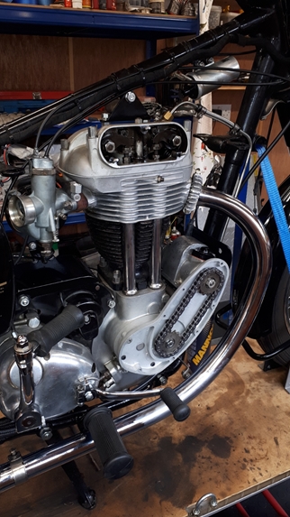
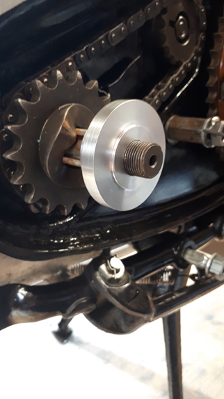 And so we come to the magneto timing. My preferred method is to set up a dial test indicator (DTI) on the top of the piston. Using that I can set the timing to the specified 1/2" before TDC very accurately. However, I was somewhat disinclined to go to all the trouble of removing the cylinder head just to set the ignition timing. Alternative methods are available. I have a very good metal timing disc that I bought from Alf Hagon's speed shop many years ago when I was building a very respectable cafe racer from an old Norton ES2... I know, don't ask! That would do very nicely if I could get it to fit onto the crankshaft. I'd already stripped off the primary drive to enable me to turn the engine over without having the gearbox and back wheel connected. I had a rummage though my box of raw materials and came up with a chunk of 2" diameter, 6082-T6 aluminium alloy. That would do very nicely, thank you. A hour on the lathe and I had an adaptor that would allow me to fit the timing disc onto the end of the drive side crankshaft axle. Another few minutes to fabricate a pointer from a short length of coat hanger wire that attached to the primary chain case securing stud and we were pretty much ready to go. Just one more thing to do... set the piston accurately to TDC. I had a spark plug body that years ago I'd modified to take a length of 1/4" diameter brass rod. That's what I used to approximately determine TDC when I set the valve clearances. I could use that, with a DTI, to accurately set the piston to TDC. I could then set the timing disc to TDC against the pointer. All is ready to set up the magneto now, but that could wait for another day!!
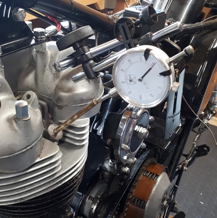
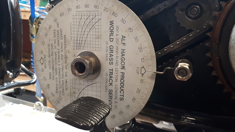
Saturday, 26th September, 2020. This next section is a bit boring, so please feel free to jump to the next interesting(?) bit. At full advance, the spark should occur when the piston is travelling up the cylinder on the compression stoke and has reached the point where is still has half an inch of travel remaining before it reaches top dead centre.  The spark occurs the instant the magneto contact points separate. The timing disc I'm using is calibrated in degrees of crankshaft rotation, not linear piston travel, so I have to determine the angle the crankshaft has still to rotate when the piston has half an inch still to travel before reaching TDC. Right... time for a brief maths lesson. You do remember what trigonometry is, don't you? Good... The engine has a stroke of 85.5mm so the distance from the centre of the crankshaft to the centre of the crank pin (con-rod big end) will be half of that... 42.75mm or 1.683" in old money. The connecting rod is 6.875" between centres (big end to gudgeon pin). The distance between the top of the piston and the centre of the gudgeon pin is fixed so we can work with the gudgeon pin at 1/2" before TDC instead of the top of the piston. At TDC, the centre of the crankshaft, the crank pin and the gudgeon pin will be in line and the distance from the crankshaft to the gudgeon pin will be 1.683" + 6.875", which will be 8.558". The crankshaft needs to be rotated so that the distance between the centre of the crankshaft and the centre of the gudgeon pin is half an inch LESS than that... 8.058". At that point, the centre of the crankshaft, the centre of the crank pin and the centre of the gudgeon pin will form a triangle and we know the length of all three sides... 1.683", 6.875" and 8.058". With that information we can use trigonometry, more specifically, the Cosine rule, to calculate the angle of crankshaft rotation. Look at the picture for an example. Trust me... the crankshaft angle that corresponds to 1/2" before TDC is 40.91° which I'll round up to 41°. Just to confuse things, the general consensus among the more knowledgeable AMC bike owners is that with modern, alcohol doped fuels, the ignition should be retarded a little... 7/16" before TDC often be quoted. Going through all the maths again gives an angle of 38.1° (call it 38°) for a linear advance of 7/16" before TDC. If I manage to set the magneto to spark anywhere between 38° and 41° before TDC, I shall be happy, but I will aim for the 38° end. Here endeth the lesson!!
Tuesday, 29th September, 2020. With the help of a little bit of pure genius, The Magneto Static Timing Light, produced by The Magneto Guys, the magneto has been timed up at exactly 39° before TDC. It was so much easier to achieve compared with my previous method of using a piece of cigarette paper between the points.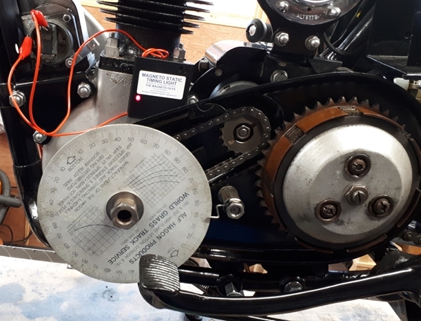
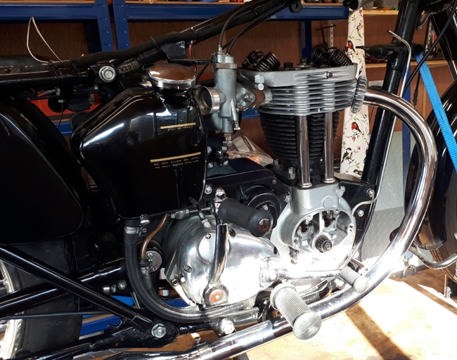
 Anyway... with that done, the primary drive was re-assembled and the chain case outer cover put back on. I did remember to put in the requisite amount of SAE50 oil. On the other side of the engine, the magneto drive chain was greased as there is no oil supply to it. Then the outer cover was screwed back into place. With the tank and seat replaced and the ignition advance lever mounted on the left hand handlebar, it was time to see Alice would start... or chuck a wobbly and refuse. Happily, she started and ran without any problems. I hope to give her a run out in the not too distant future.
Friday, 2nd October, 2020. Well, that didn't turn out as I expected. A 50 mile run down to Peterborough and back was totally uneventful. Alice ran perfectly and didn't miss a beat. It wasn't until I got back that I realised that I had a serious oil leak from somewhere at the top of the engine. The cylinder head and rocker box were covered in oil, to say nothing of my jeans! Alice went straight back into the workshop and up on the bench again. With the seat and tank off, I cleaned away all the oil and looked for the source of the leak. The rocker box had been put back with a new gasket and all the bolts were tight so I didn't think the oil was coming from there. Then I spotted a likely cause... The de-compressor / exhaust valve lifter shaft had worked it's way out of the rocker box until the 'O' ring oil seal was clear of the rocker box casting. It's not a particularly bright design in as much as the only thing holding it in place was the return spring and that was a 'pattern' replacement which wasn't that well made either. The spring is held in place by a small, 2BA screw, however, the end of the spring that the screw secures was too long, allowing too much lateral movement of the valve lifter shaft. I took it all apart, cleaned it up and replaced the 'O' ring seal. I also, with the aid of some red heat, reformed and shortened the spring arm, keeping the shaft correctly located.
I put the tank back on temporarily to fill the carburettor and started the engine on the bench. I ran it for about 5 minutes and there was no oil coming from the valve lifter... great, job done. It was only then that I noticed the small puddle of oil collecting on the work bench. Oil was dripping from one end of the short piece of hose that connects the two parts of the oil feed pipe to the rocker box. The rubber had hardened and was no longer oil tight. I replaced it with a new piece of hose and two new clips. This time, the job was a good 'un and Alice is now oil tight again.
Friday, 18th August, 2023. Alice has been seriously neglected over the last three years or so. Life, and five other bikes to ride got in the way. In fact, she has been under a dust sheet in the far corner of the garage for the last 18 months. I decided that it was time she saw the sun again, so a few days ago, I pulled her out of the garage for a pre-ride check. First thing I found was that the battery was completely dead. It had been connected to a battery maintenance charger but had died anyway. A new battery has been fitted. There was some petrol in the tank but she stubbornly refused to even cough, let alone start. That petrol was drained and disposed of in an approved manner... Tipped into the Honda tank as that will run on anything! With the carburettor drained and a gallon of fresh petrol in the tank I attempted to start her again... Still nothing. The spark plug was removed and cleaned and I dragged some fine emery paper through the magneto points to remove any oxidisation. This time she fired and ran. Hooray! I let her run for a few minutes; to warm up and make sure any residual oil in the crankcase was being pumped back to the tank. There was no sign of any oil leaks so the tyre pressures were checked and brought up to the correct pressure.
Yesterday I took her out for a run. We covered about 70 trouble free miles. I'd almost forgotten just how much I enjoyed riding her. It won't be so long before I ride her again.
Sunday, 21st July, 2024. Yeah... Right. Well it's been the best part of a year, so yesterday, Alice and I went for a bit of a blast to Peterborough and back. She started reasonably easily and ran like a dream for the 50 or so miles, but the cylinder head and barrel were covered in oil when I got back home. I whipped the seat and tank off this morning to find that the nut securing the oil feed pipe to the rockers had come loose. An easy fix and after a thorough clean, she's now back in the garage. I'll run her down to the Strath on Wednesday.
Link to G3 parts as bought from Malcolm.
Link to Index and Home Page.
Link to Matchless G3/LS - Part 1.
Link to Matchless G3/LS - Part 2.
Link to AJS M18S page.
Link to Triumph T120R Bonneville page.
Link to Triumph Tiger 90 page.
Link to Matchless G80CS page.
Link to Honda VFR750 page.
Link to Norton 650SS page.
Last updated 21/07/2024.